The test stands are designed to investigate the endurance of drive train components, such as gear boxes, bearings, and drive shafts, while simulating flight loading conditions. To address certain types of mechanical failures, USC is currently focused on the condition based maintenance of the tail rotor drive train (TRDT) and main rotor swashplate (MRSP) of the AH-64, as well as the auxiliary power unit (APU) of the UH-60. The purpose of predictive maintenance (PM) research at USC is to predict failures before they happen, extend the amount of time a component can be run and understand when a component becomes unsafe. Testing conducted on the TRDT, MRSP, and APU furthers the objectives of PM. These experiments through their unique design, allow the stands to simulate flight loads experienced by the aircraft. The test stand’s goal is to discover new condition indicators (CIs) while validating existing CIs. Current military CIs are calculated using vibration data collected by the Modern Signal Processing Unit (MSPU). Data is gathered by simulating flight loads on components with faults which have naturally occurred in the field or are induced in a laboratory. Testing conducted on these stands has led to modifications in military maintenance procedures, resulting in cost savings for the military, as well as increases in morale and safety.
Test Stand Configurations
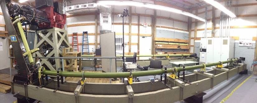
The TRDT allows multiple components from the AH-64 to be evaluated simultaneously. The test stand can also be configured to run articles from other airframes including the UH-60 and CH-47. Components on the stand are the forward hanger bearing, aft hanger bearing, intermediate gearbox, tail rotor gearbox, and tail rotor swashplate. These components are driven by a computer controlled 800 HP motor that can achieve 150% of the normal operating speed of the aircraft. Torque is generated by a similar motor that is connected to the output shaft and able to place a load of at least 1200ft-lbs on the system while also generating up to 70% of the energy to be put back into the original motor. The test stand can replicate the loads that are normally experienced by the TRDT during flight. The testing configuration also has a 1.2° misalignment in the drive train to expedite wear. An additional benefit is that more sensors and new aircraft applications (i.e. lubrication) can be tested. For example, adding strain gauges to the pitch links creates the opportunity to verify the pitch link loads.
This test stand is designed to test the main rotor swashplate for an Apache helicopter. The stand is actuated by a 50 HP electric motor with a drive shaft and a 90° gearbox that can operate at up to 150% of the normal speed. The rotor head is mounted using a taper at the top of a vertical drive shaft extending out of the static mast. Rotation is transmitted to the swashplate through four pitch links, which are connected to the rotor head. Hydraulic cylinders are used to input loading conditions seen during flight. The speed of the drive motor and hydraulic pressure is easily controlled, making over speed and over load testing simple. Vibration data is collected and processed from the swashplate through the MSPU (Modernized Signal Processing Unit).
The experimental drive train test stand is capable of being used as either a preliminary test bed for components before moving to the full-load test stand or reconfigured to accommodate other drive train systems. Currently, the no-load test stand is set up similarly to the tail rotor drive train test stand. The test stand is driven by a 5 horsepower motor and has no misalignment. When configured to be a UH-60 test stand, the tail rotor drive train output motor is turned 180° to accommodate a Blackhawk tail boom and the input motor is slid down the rails to be used on the drive train.
The auxiliary power unit (APU) test stand is designed to run a UH-60 APU at full flight speed and loading. This test stand is instrumented with standard component sensors with the addition of temperature, vibration, and torque measurements to help further evaluate the article’s condition. Exhaust gas temperature and oil temperature are recorded. The output speed and torque of the APU will be monitored with a dynamometer. This test stand can help further develop future sensor and lubrication prototypes for aircraft turbine applications.